
ION

Greetings humans, welcome to the first issue of the Ionic Skies newsletter!
For a brief intro, we are building an ionic wind aircraft for our capstone project. Ionic wind is an entirely new form of aircraft propulsion that is silent and has no moving parts. That makes it well suited for low-and-slow drone applications: 3D mapping, ecological monitoring, and infrastructure inspection. However, low-and-slow drone applications also require high flight distances, which ionic wind cannot currently provide. The goal of our project is to design a more efficient aircraft than our predecessors at MIT by improving the performance of the airframe, power converter, and thrusters. Throughout the year we’ll convey the process with our newsletter.
Below is a quick section on our inspiration, after which you’ll see photos and videos from our development process. Please check out our roster at ionicskies.com so you can match names to faces.
The month of October was spent finishing off our first prototype designs and starting prototype builds. So you will see mostly design pictures and infant prototypes.
Let’s jump in.
Background (only for this issue)
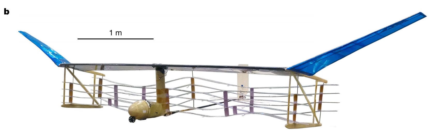
Here is the first ionic wind aircraft that ever flew, at MIT. In the yellow nose sits a 200V battery pack and a 200V-40kV DC-DC power converter. There are 8 thruster pairs on this aircraft, all hanging below the wing.
Some improvements/changes we will try to make to this aircraft:
Electronics payload inside wing, eliminating bulky nose
Tensioned thrusters above and below the wing for increased strength
Use wing as part of a thruster, and part of cooling system
Dielectric barrier discharge rather than DC Corona discharge on thrusters
Use active control for stability as opposed to dihedral wingtips (in blue)
Airframe

Our finalized mule airframe design. We plan to only glide test it with a dummy payload and dummy thrusters. It has payload capacity in the wing (improvement 1), and it also has thrusters below, above, and integrated into the wing (improvement 2/3).
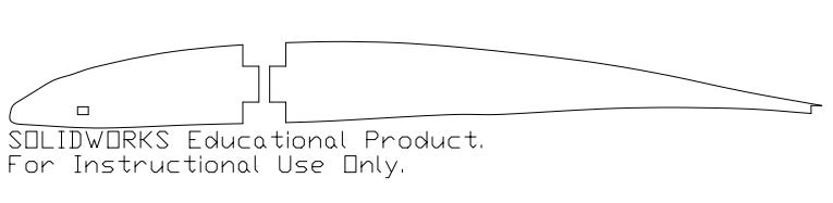
Drawing for airframe ribs that were sent to the CNSI Innovation Lab to be lasercut from foam and balsa.
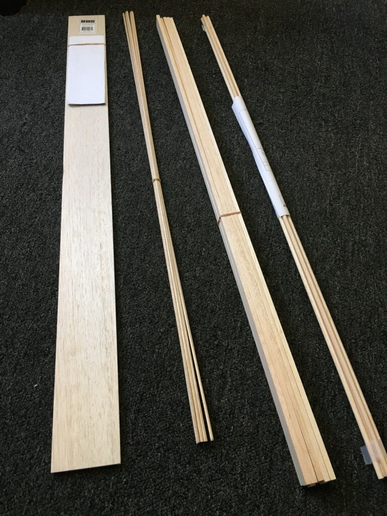
Balsa raw material at Sam’s house. Believe it or not, these will turn into an aircraft.
Power Converter
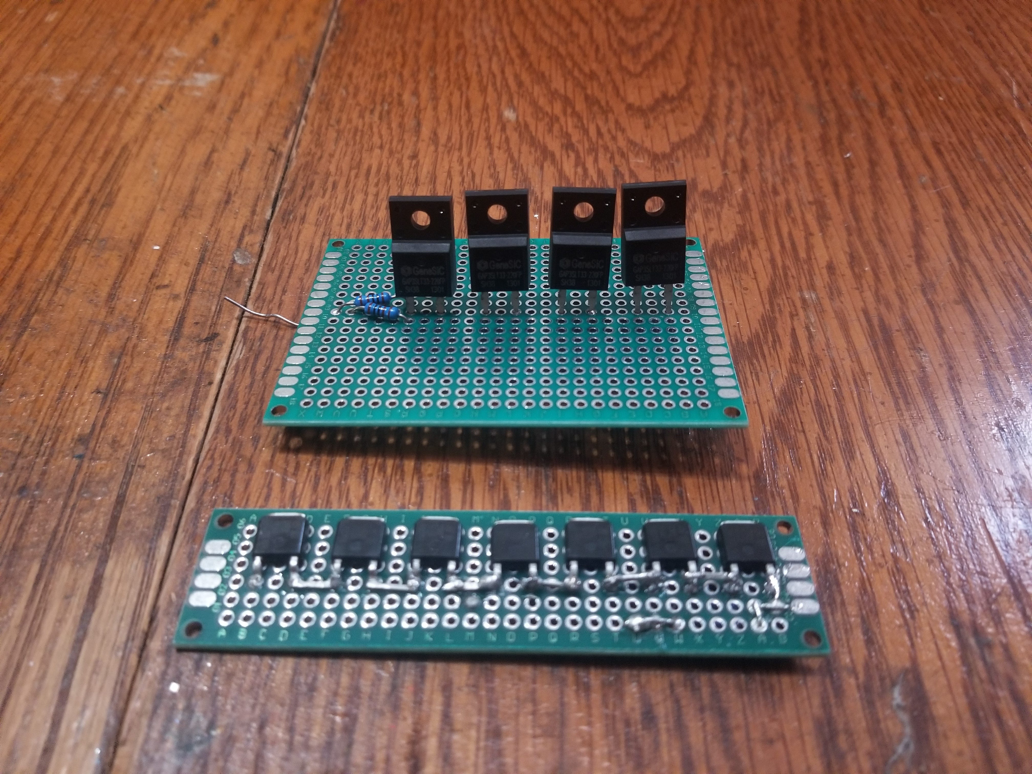
These are simple diode test circuits that Katiria and Bobby put together for low voltage high frequency testing of the diodes that will be used in the voltage multiplier.
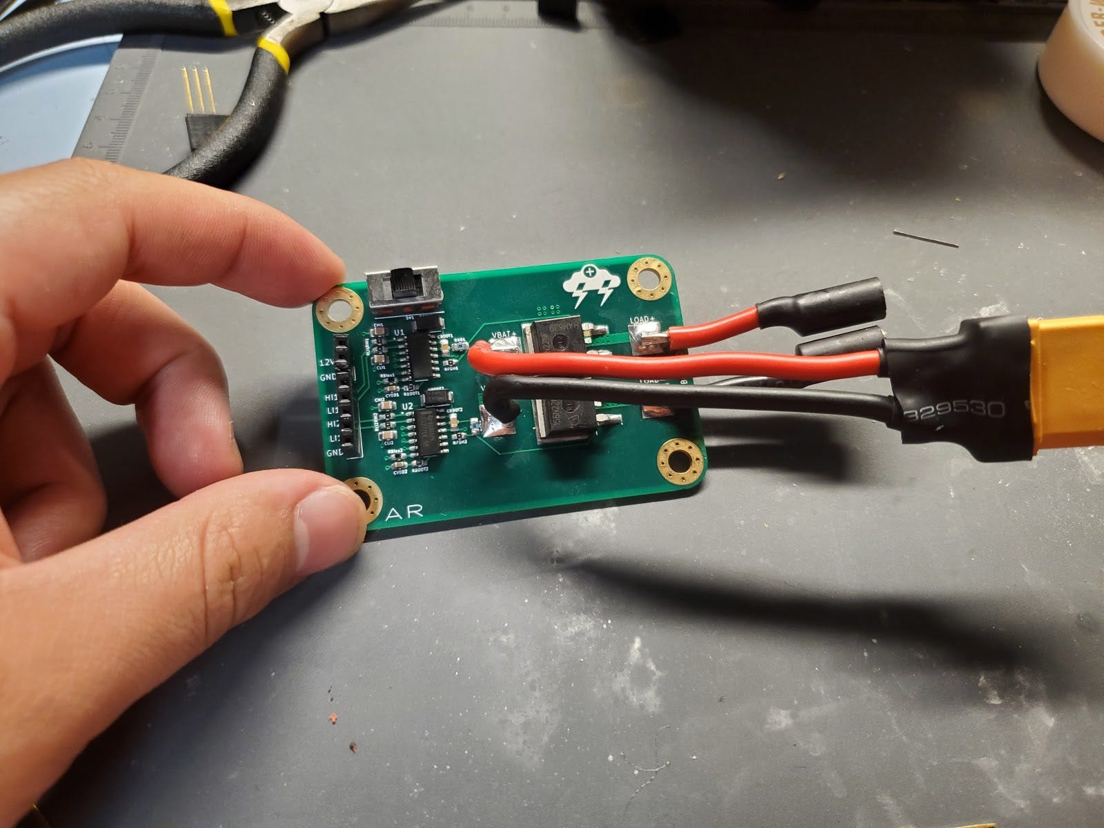
This is the H-bridge driver PCB that Alex designed. Statement that will soon be tested: it’s capable of switching on and off hundreds of volts at hundreds of kilohertz.
Thruster
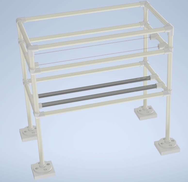
CAD model that Dylan made, of the thruster test buck that we will use for thrust measurement from DC Corona Discharge. (This one’s been around for a while)
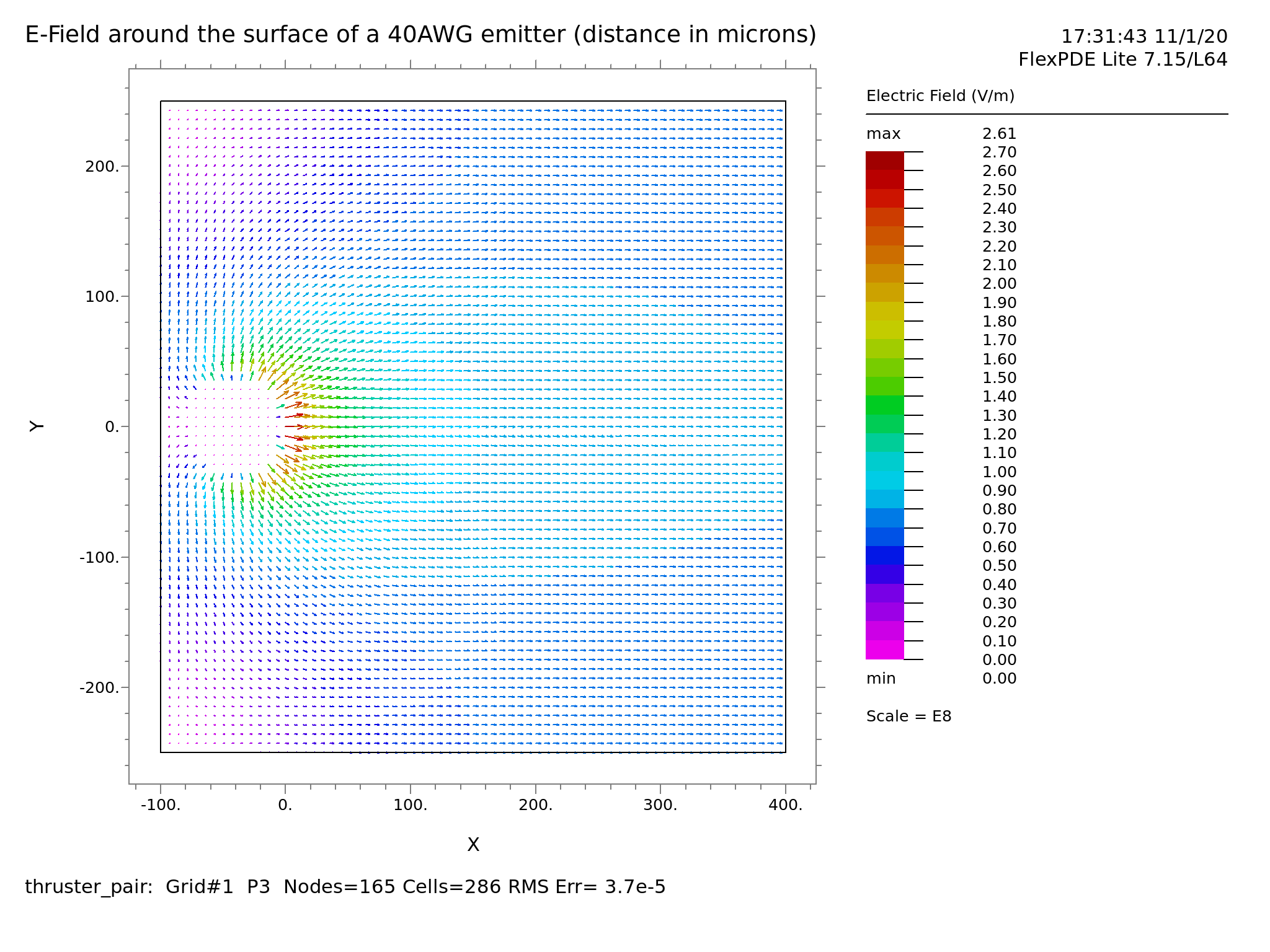
E-field lines for infinite wire-to-plane geometry, which Dylan generated using FlexPDE. We are especially interested in the red region because that is where the ionization of air molecules occurs.
Launcher
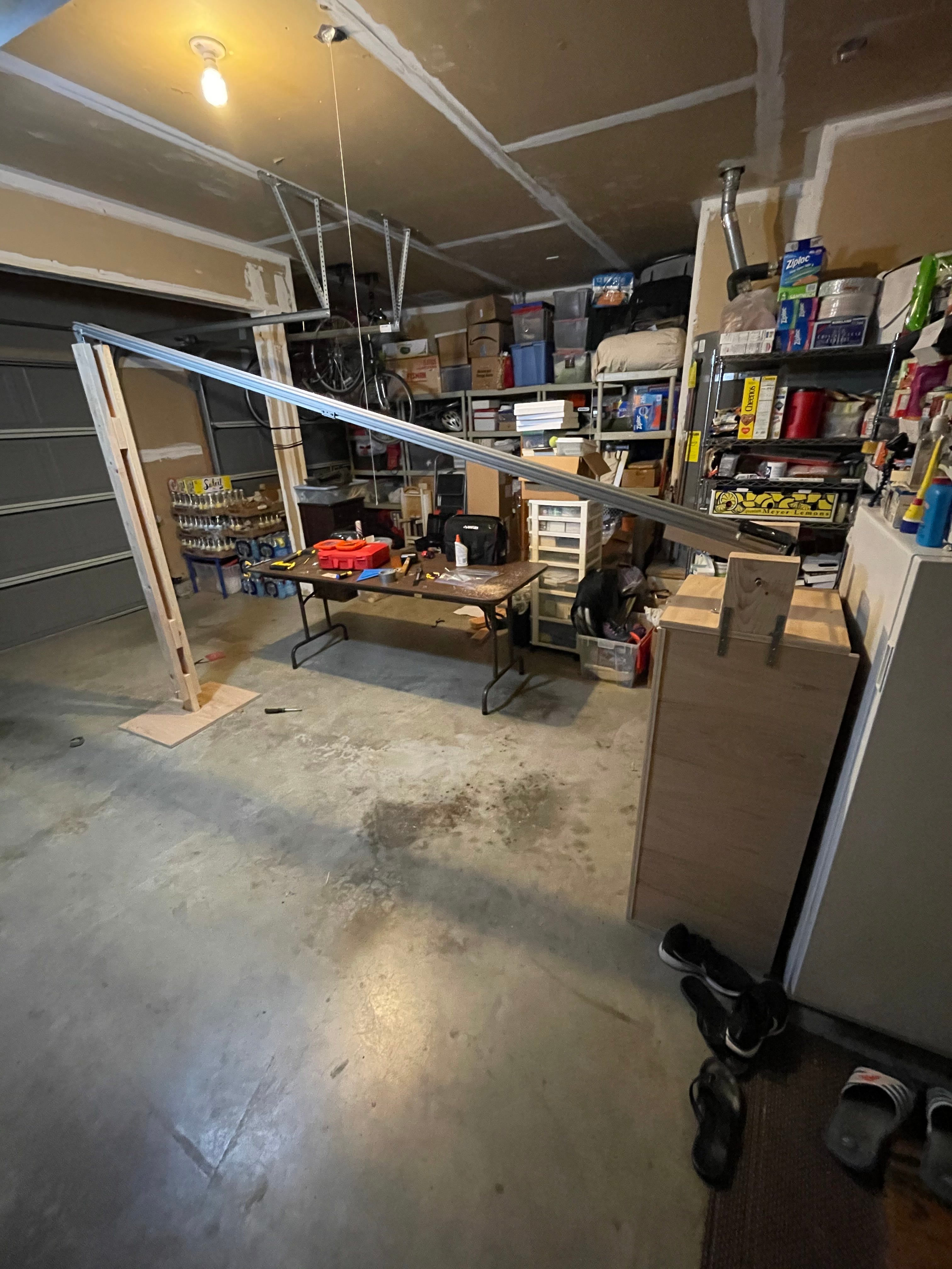
The purpose of our launcher is to accelerate the aircraft to its steady state speed, at any angle between 0 and 15 degrees. Here it is, standing at maximum angle in Ryan’s garage. It operates using a falling weight and pulley system. Note the size of the table and garage door - this launcher is a beast.
That wraps it up for October. In November we’ll build and test each of our prototypes. That means the launcher will send tangerines across Isla Vista, the airframe will be bumped off the cliffs onlooking the beaches, and I’m not going to joke about high voltage thruster testing. In short, the November issue will be at least twice as interesting.
If you have any questions at all, feel free to email me at mihir00@ucsb.edu. That’s all folks, thanks for reading!