
ION

Welcome back to the Ionic Skies newsletter!
If you are new and want some background, please skim through our October issue, accessible here.
It ended up making sense to skip a month since what we wanted to show in November only ended up materializing in December. I suppose that’s how these things work, but beware - this issue covers a lot.
We now have working prototypes for pretty much all our subsystems, which you will see below. The only exception is the thruster test buck, since we are still looking for advising and supervision from a high voltage expert to safely turn it on.
Here is the breakdown of subsystem updates in this newsletter:
Airframe: 7 pictures
Converter: 9 pictures
Thruster: 2 pictures
Launcher: 2 picture
Without further ado … the subsystems.
Airframe

Who knew mules could glide! Keep reading for the (not yet finished) story of The Mule.
CAD model

This is the finalized CAD model of the mule prototype. What we have in the video above is everything in this CAD model, minus the wingtips and the thrusters.
Main spar and fuselage ribs
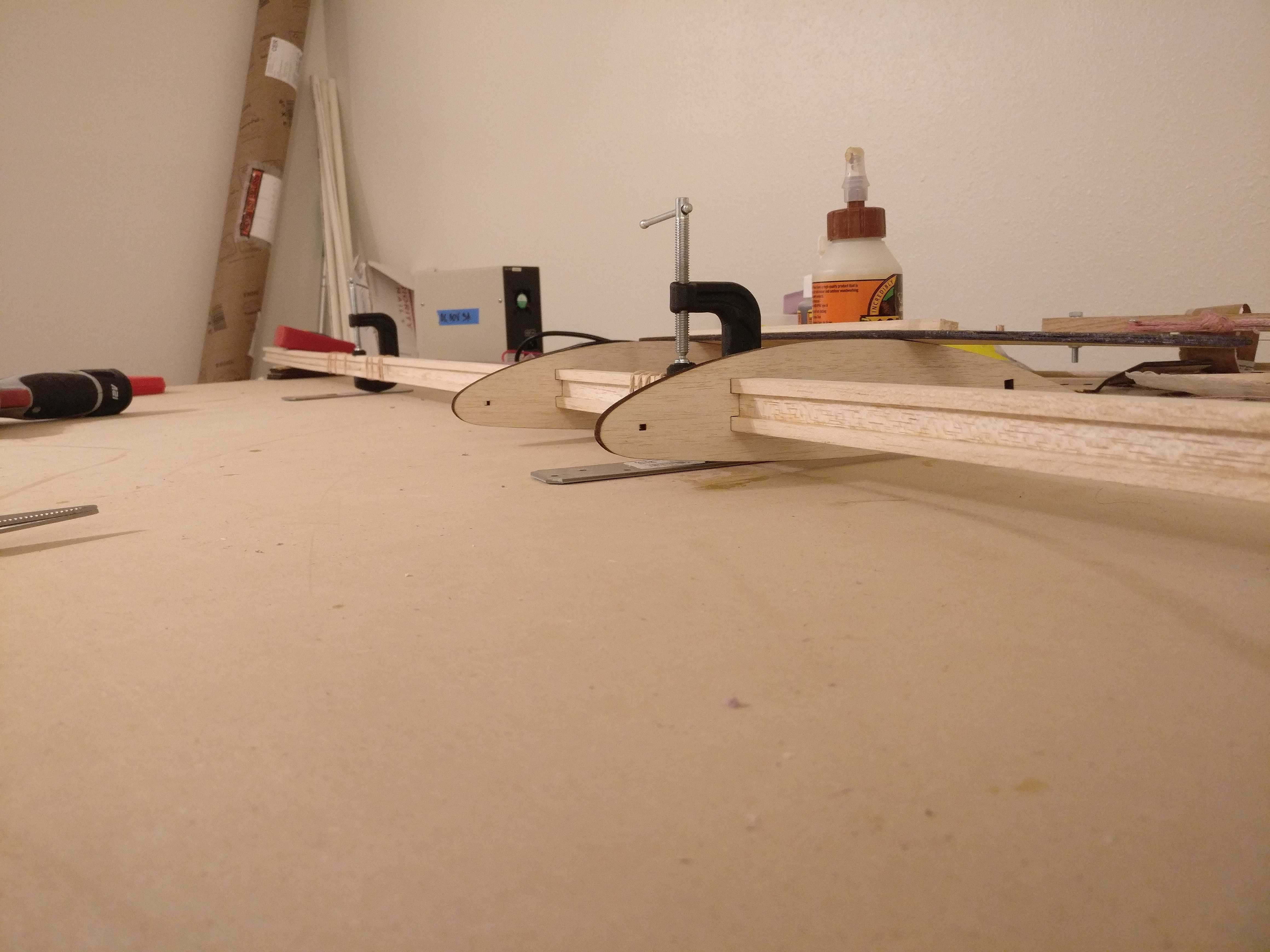
The build started with the main spar and the fuselage ribs. The main spar forms the structure along the wingspan, and the fuselage ribs form the structure of the fuselage.
Spar, fuselage, wing ribs
Here we have all ribs glued except the central four. Ribs were designed in two pieces, which fit the front and back of the I-beam spar.
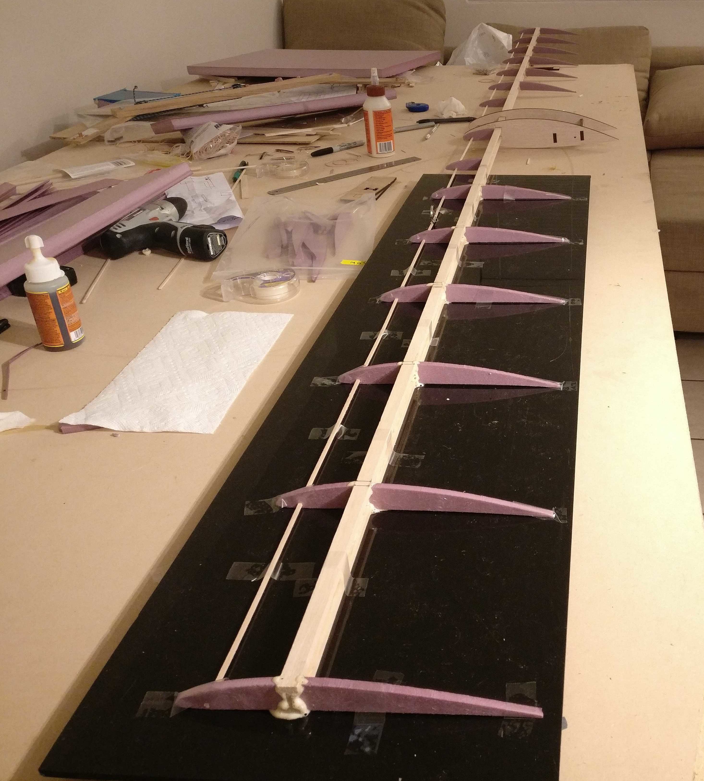
Unwrapped airframe

Here is the airframe structure in all its glory. The foam ribs are supported in the leading edge with foam profiles, and in the trailing edge with balsa stringers.
Hot wire knife
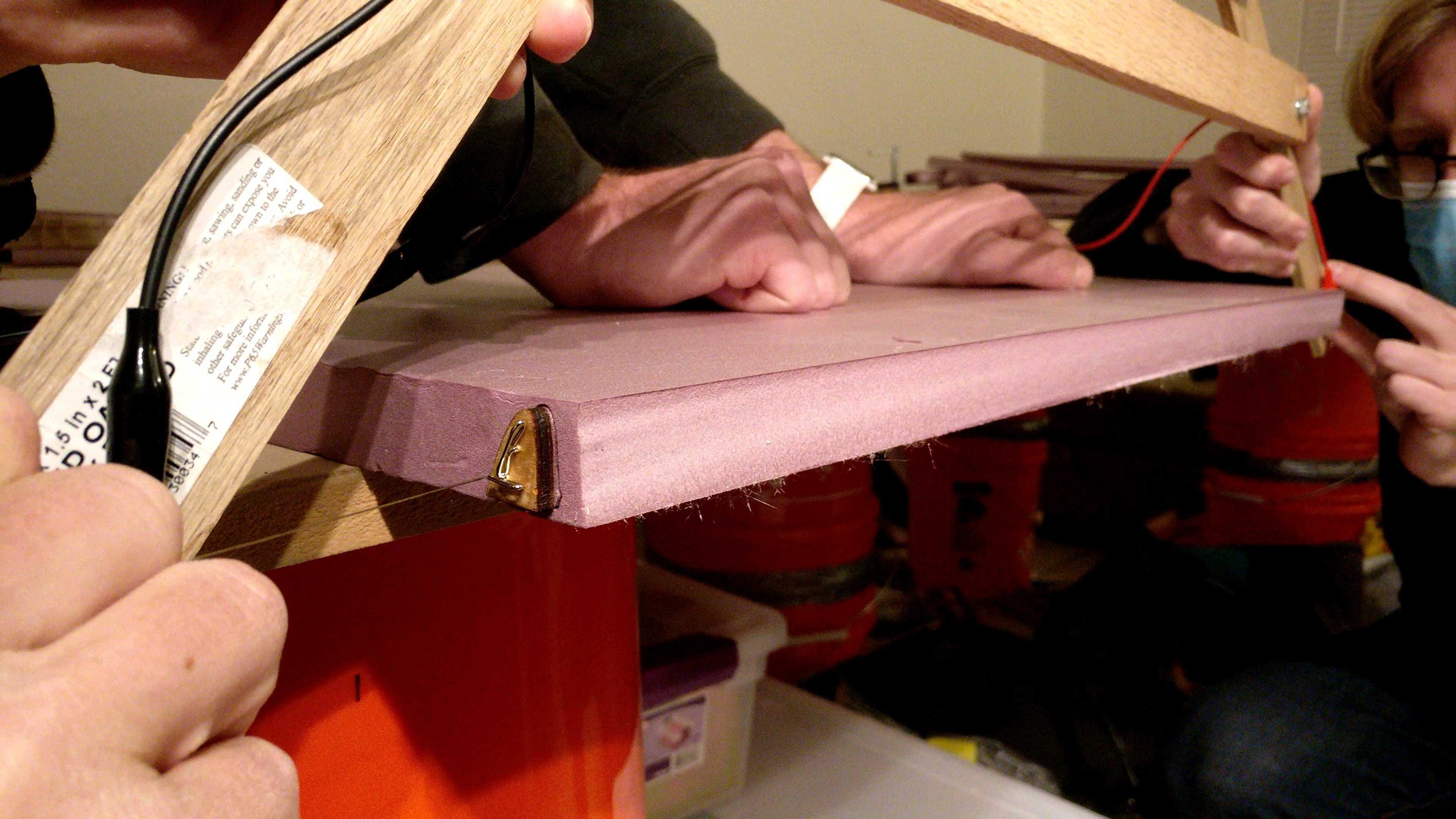
We use our hot wire knife for cutting large foam extrusions, like the wingtips and leading edges, while the foam ribs are laser cut.
Wrapped airframe
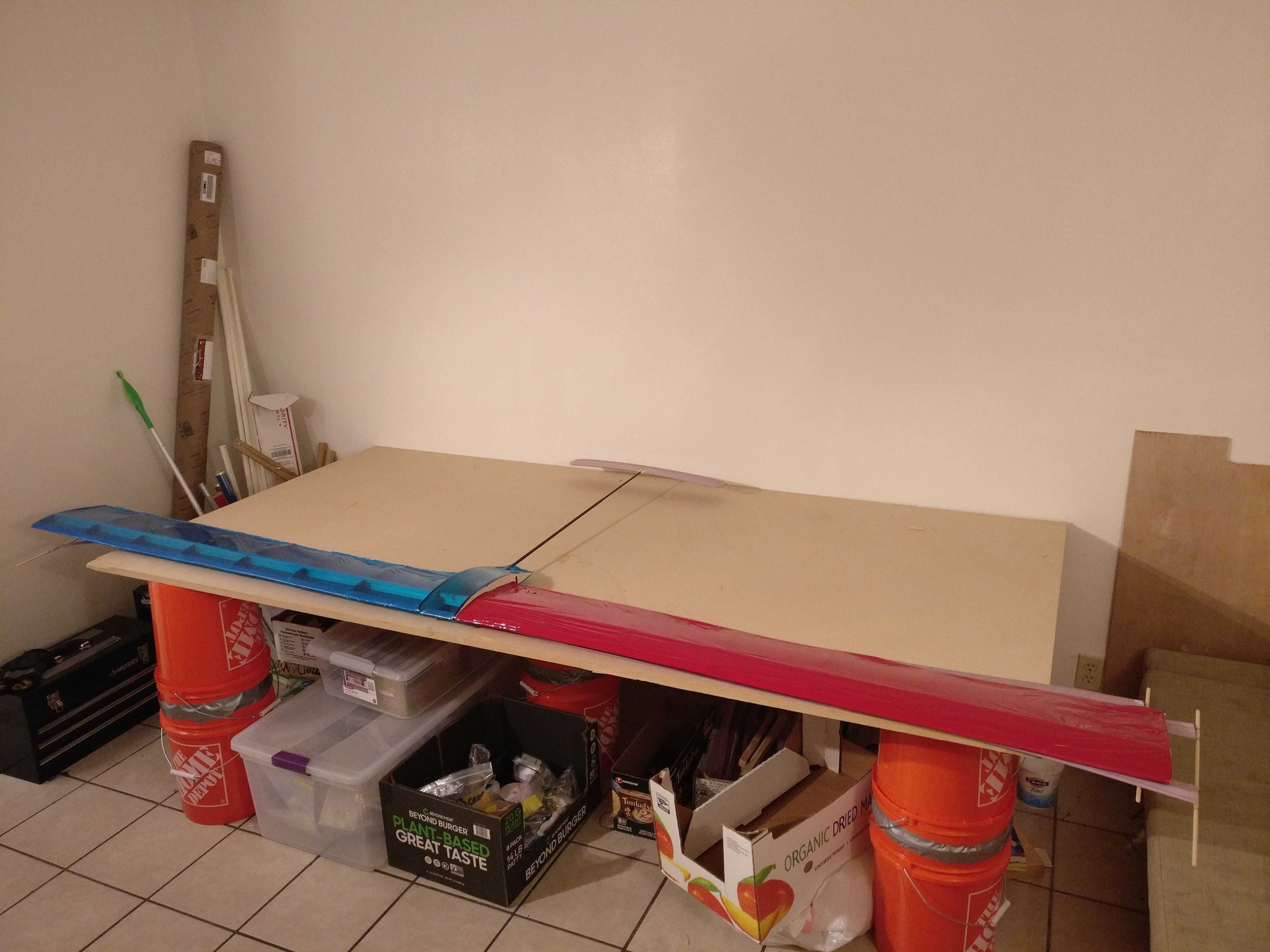
This is the airworthy mule from the video, weighing in at 230g. A light and tough plastic wrap has been ironed around the airframe structure in the previous picture to increase strength and complete the airfoil shape.
Next steps
Glide testing with and without the launcher will commence in early January, as soon as the wingtips and collector airfoils are completed. Our next prototype The Stallion will be built in parallel. It is designed for full integration with the other subsystems.
Converter
Recall that the power converter is supposed to convert a DC input in the 100s of volts to a DC output in the 10000s of volts. It does this through three stages:
a switching stage which chops up the DC input into an AC square wave
a gain stage which turns the AC square wave into a sine wave with ~40x gain
a rectifying stage which converts the AC sine wave into DC output with ~5x gain
Each stage has completed proof of concept testing and will be discussed below.
Switching Stage
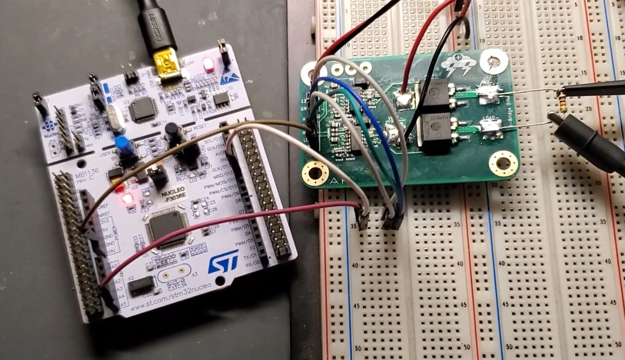
On the left is an STM32 development board used to generate a reliable high frequency square wave output. The green board on the right is our custom developed H-bridge switching circuit.
The H-bridge passes a DC reference through the load with alternating polarity. This is how we turn our DC reference into a square wave.
4kHz switching
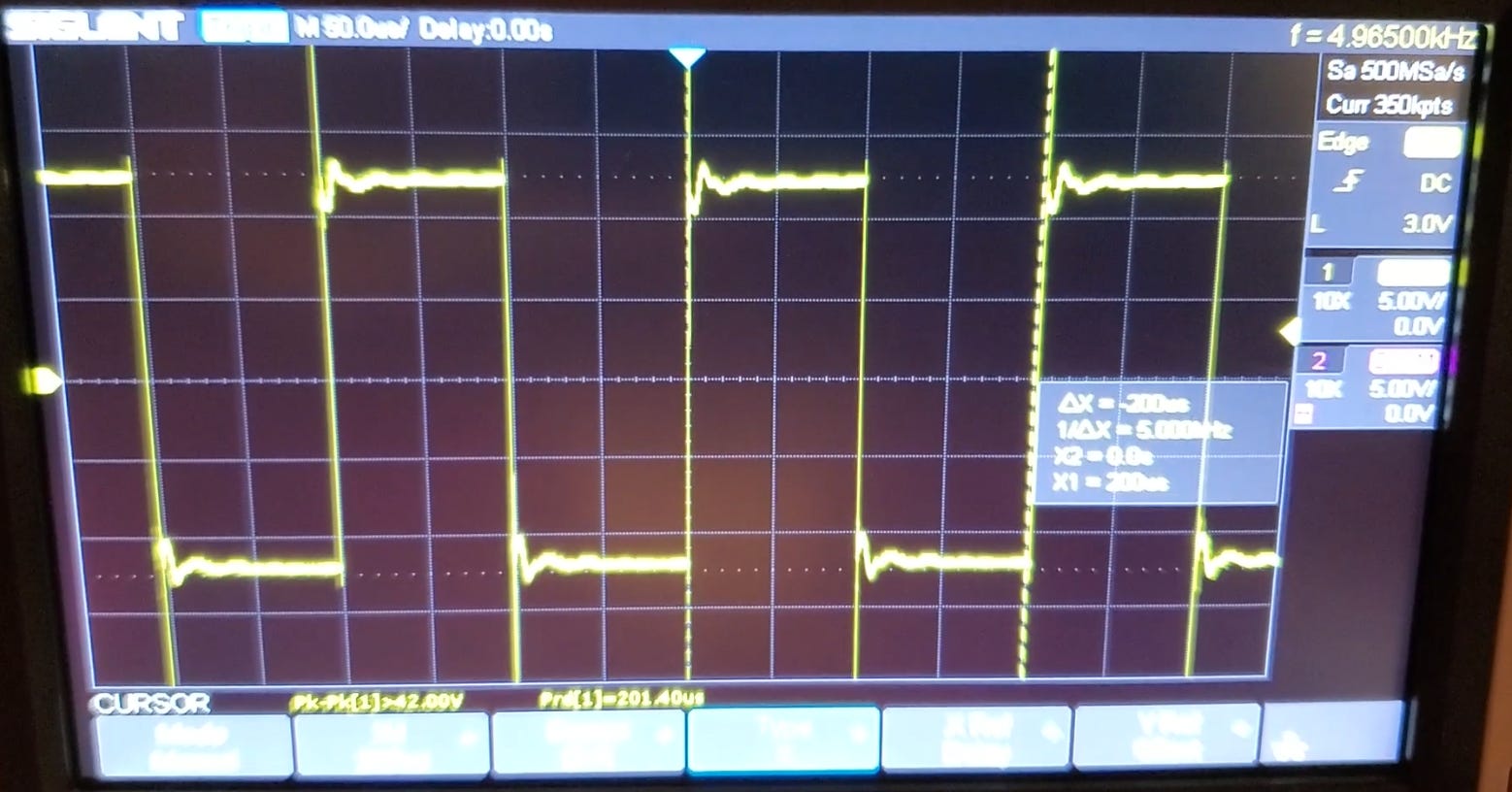
Here is the 12V 4kHz H-bridge output. Notice the small undamped oscillations after every switch, called ringing. This will get worse at higher voltages and frequencies.
80kHz switching
At 12V 80kHz the ringing is significantly worse. Getting a clean square wave with our inductive load at 200V and 250kHz is the focus of our next switching stage prototypes.
Gain Stage
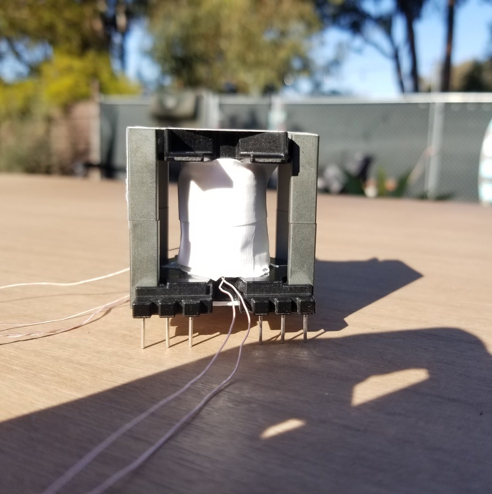
Here is our 5x gain transformer. We built it with a plastic bobbin, Litz wire, and a lightweight ferrite core for high frequency applications.
A 15x gain transformer requires very careful construction and a custom bobbin for high voltages, so we decided to stick with 5x gain to get practice.
Transformer frequency sweep

Shown here is a frequency sweep from 100 to 400kHz, with gain ranging from 4 to 8.
Rectifying Stage
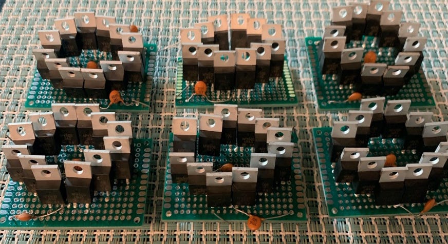
This is the first prototype of our rectifying stage, from which we got a 4.8x gain.
This contains multiple full bridge rectifier structures, hence the diamond arrangement of the diodes on each board. Series diodes are used to increase reverse voltage drops.
Multiplier PCBs

We designed a PCB to handle our full input and output voltages (8kV to 40kV), allow mounting of heat sinks, and integrate with a standardized test fixture.
Multiplier Test Fixture

This is our multiplier test fixture, meant to make testing the multiplier PCBs safe at voltages past 40kV. It will allow us to probe node voltages using custom connectors, and discharge all capacitors with a custom discharge tool.
Machined test fixture pieces
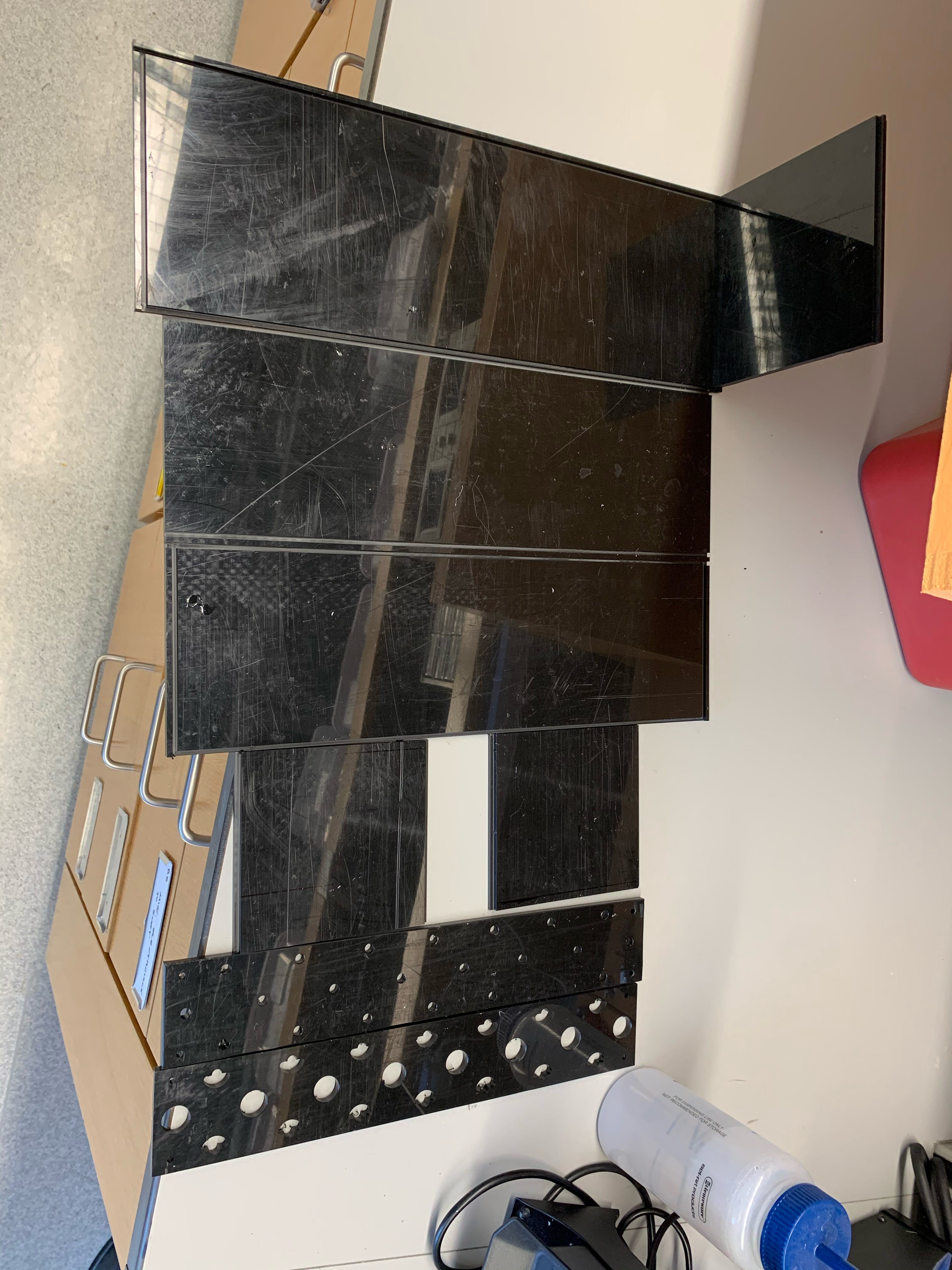
Most of the parts of the multiplier test fixture have been machined, so we are close to being able to assemble this fixture.
Next steps
All the prototypes shown above are undergoing revisions and improvements to help us scale up voltages and power outputs. We are working on cohesive test setups and procedures to allow safe testing of all stages.
Thruster
Recall that thrusters work by ionizing and accelerating air molecules using pairs of electrodes that are given high voltages by the power converter. Thrust generation is highly dependent on thruster geometries, materials, and voltages. Therefore, we want to work on testing such configurations, and we will do so with our thruster test buck.
Thruster test buck
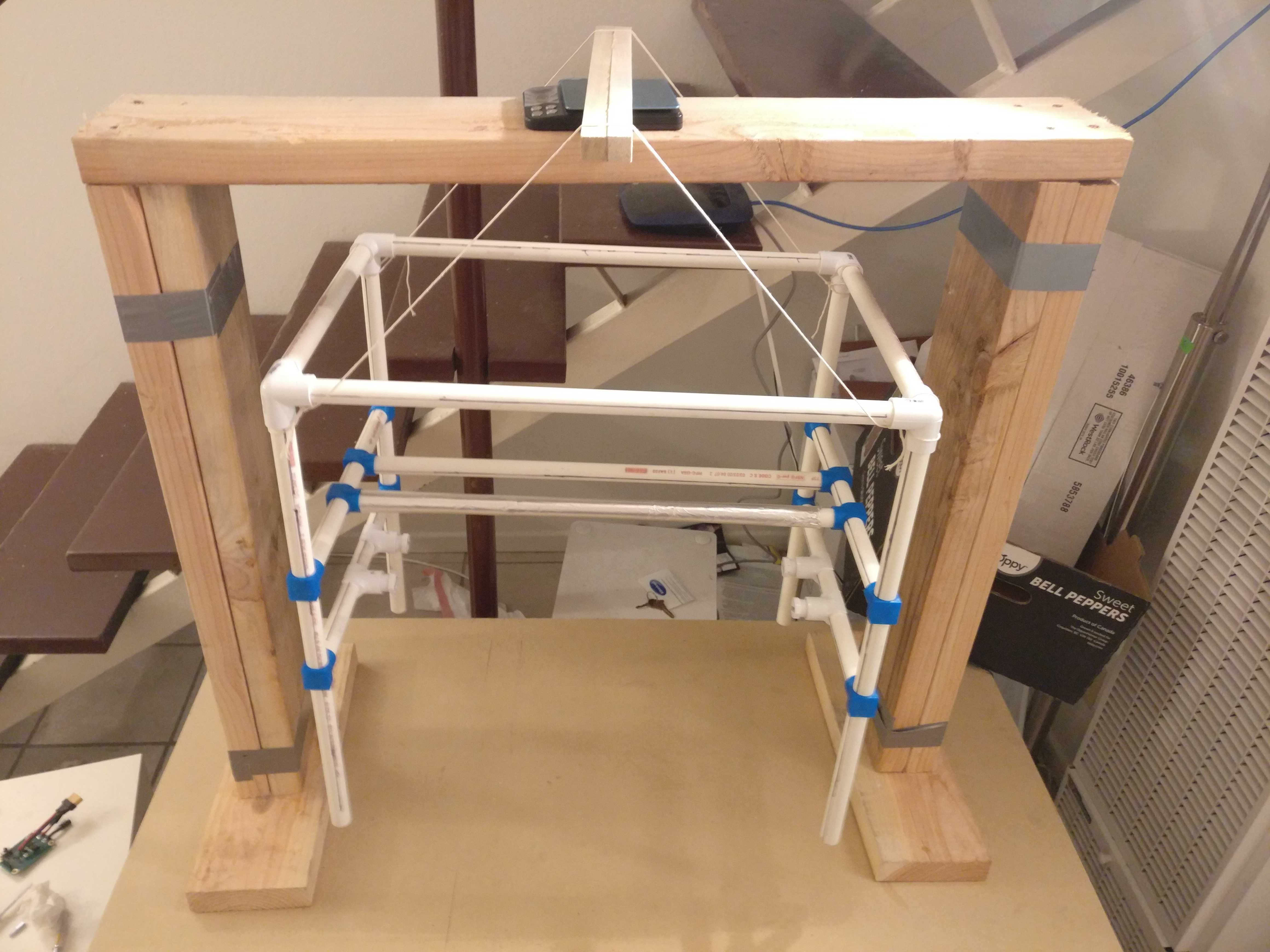
Our thruster test buck allows for testing of 1-6 thruster pairs in various configurations, generating up to 18g of thrust.
Thruster pair
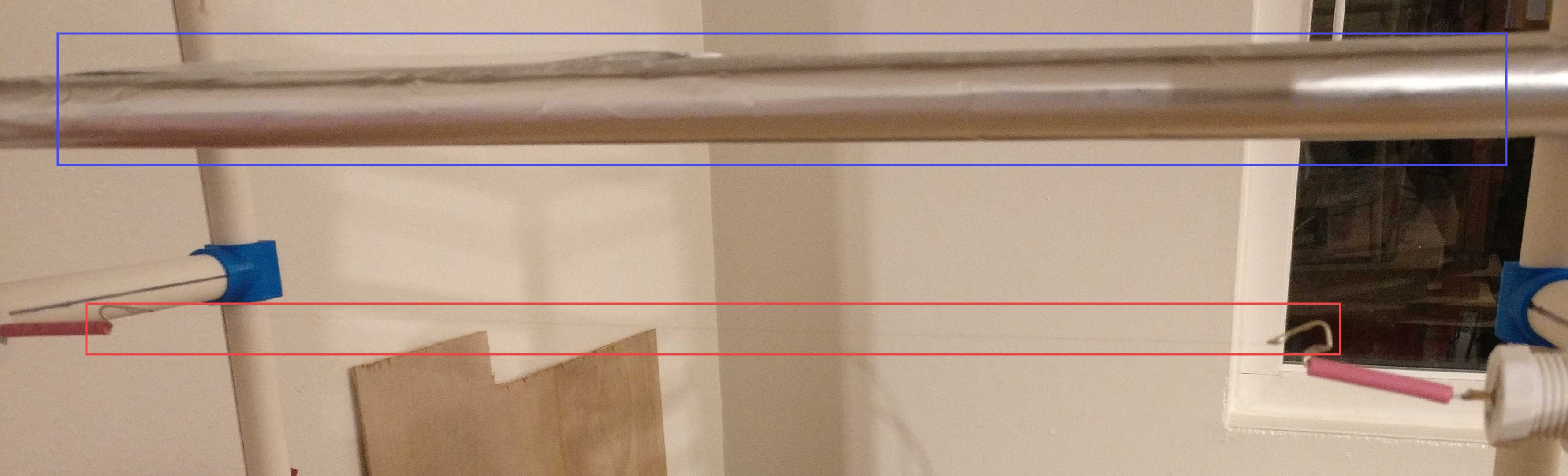
This is a thruster electrode pair up close. The collecting electrode, in the blue rectangle, is made of a PVC pipe (like from the previous picture) wrapped in aluminum foil. The emitting electrode, in the red rectangle, is made of a 40AWG (0.08mm diameter) copper wire. It is very barely visible in this picture.
Next steps
Next quarter we hope to obtain advising and approval from a high voltage expert to safely turn the test buck on. We plan to test a variety of thruster configurations and materials to help us optimize our thruster design.
Launcher
Our launcher prototype successfully launched a 2.5kg concrete sack at an angle of about 10 degrees, at 5m/s. The launcher allows easy of adjustment of both launch angle and launch acceleration.
Linkage
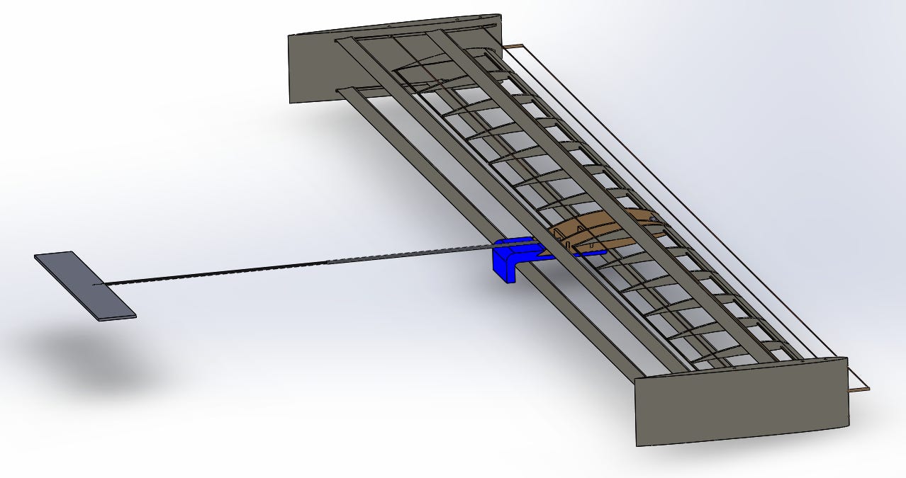
Highlighted in blue is the linkage that holds the airframe snug with the launcher’s gantry cart during launch and only allows forward motion of the airframe.
Next steps
We want to insulate the launcher to eliminate risk of arcing, and to complete the linkage that will connect the gantry cart to the airframe fuselage.
The End
That concludes the December issue of our newsletter! That also wraps up our fall quarter. There is a lot of testing and integration to be done before we have a flying aircraft, so the quarters approaching will be quite a ride.
Thanks for reading!